The following article was originally published by Emobility Engineering magazine, published April 11, 2024Read the original article
A focus on design-for-manufacture and assembly has also been key in the development of several key innovations found within the motor.
Touted as the future of EV propulsion, axial flux motors are more compact, lighter and offer higher power and torque densities than their radial flux counterparts. Until now, they have been exceedingly hard to build but Traxial, a subsidiary of Magnax, is aiming to change the game with a new design methodology that could take this to the mainstream.
The Belgium-based company’s design-for-manufacture approach to its motor has resulted in a solution that minimises the number of parts required, maximises the ease of automation in assembly, minimises material use and ensures the crucial tolerances can be achieved in mass production.
Traxial’s Operations and Systems Engineering manager, Gianluca Lioce, explained: “Today, in the prototyping phase, without automation, we can produce two sample motors per day with just four people. With current equipment and more resources, we can provide a capacity of 3000 motors per year, which could support the scaling up of a manufacturing partner.
“In the future, we can certainly reach a level of automation that can allow us standard rates of production. We had to consider the tolerance that can be handled by a robot and not a human, so this is a compromise between performance and manufacturability. The stator of axial flux motors, historically, was very difficult to produce but at Traxial,,all the parts have been designed to be easily automated in the future.”
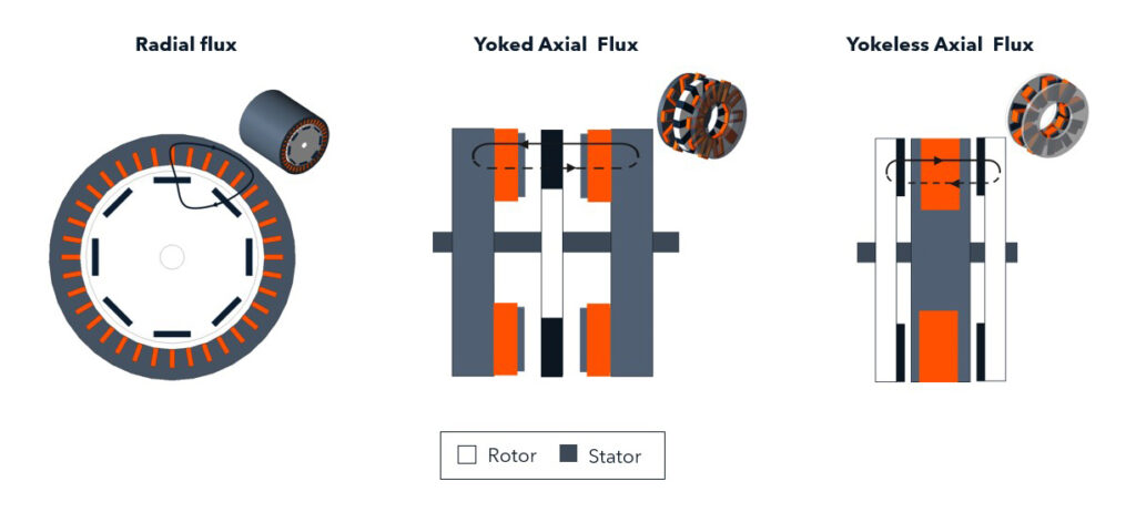
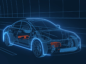
The radial and axial flux electric machine topologies
Axial Flux motor approaches
There are two different design approaches to creating an axial flux motor: two rotors with one stator or one rotor with two stators. The design with two rotors, known as a ‘yokeless’ axial flux motor, maximises the benefits of the design. In a yokeless axial flux motor, the magnetic flux travels axially (along the axis of rotation) through the air gap between the rotor and the stator. This design facilitates a shorter flux path and a more direct application of force to the rotor.
Since the axial flux motor often features two rotors sandwiching a single stator, it effectively doubles the active surface area for magnetic interaction compared to a single-sided design, without a significant increase in the volume or weight of the motor. This leads to a higher torque density, because the motor can generate more torque per unit volume. This is the design used by Traxial and is seen as most likely to revolutionise the EV market.
The Traxial motor promises up to 3x the torque density and up to 2x power density when compared to existing EV motors and, crucially, it achieves this with a unit measuring around one third of the axial length of a typical radial flux design. This results in a lower mass, giving EV makers more freedom to implement compact dual motor EDU setups for torque vectoring, which positively impact the driving dynamics.
The design brings significant benefits but also manufacturing challenges. These include the extreme tolerances required for the air gap between the rotor and the stator; the centrifugal forces caused by the higher running speeds; and the dissipation of heat created, as the motor windings are located deep inside the motor.
The biggest challenge, however, is the ‘yokeless’ single stator – dual rotor topology, which requires an innovative way to position and hold the stator teeth in place. This is one of the key areas in which Traxial has pioneered new technology, creating a unique design that Lioce says is still “trade secret” but that is, crucially, cheap and easy to automate in manufacturing.
Traxial innovations
Traxial is now on its second machine generation and has so far reduced the number of parts by 30% compared to its first generation design. Technology Strategy and Commercialisation Director James Byatt says this is key to its success and explained: “There are two factors that influence the manufacturing cost from an OEM’s perspective: material weight and number of parts. A lightweight motor, quite simply, has lower material costs, while the number of different parts required has a big effect on the sourcing, overheads and logistics of the supply chain. The fewer number of parts, the fewer manufacturing steps to build the motor. This is fundamental to the overall cost.”
Motor windings
The Traxial design has individual stator cores, each of which has a discrete coil of flat copper wire wound around it. This completely separates the coiling and assembly processes, making it highly efficient when it comes to automation. The reduced copper overhang, meanwhile, achieves 50% more efficient use of copper, reducing weight of materials.
“In our design, the windings and the core insulation are very simple parts and then you have the core itself,” explained Lioce. “All the windings are laser welded to the busbar and manufacturing can be automated using a robotic laser welding machine, which is standard equipment that every OEM uses today in production.”
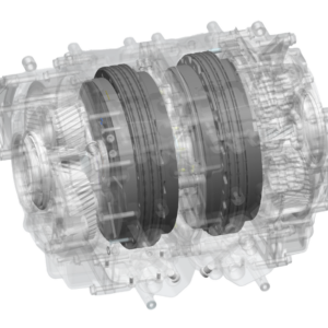
Cooling system and Clamshell core
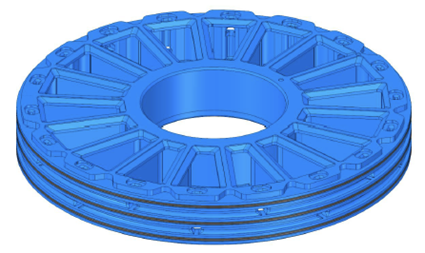
The key to the design is a clamshell (below left), which holds the individual stator teeth in place. This not only overcomes the challenge of stator positioning in a yokeless design but also integrates with the ‘direct oil cooling’ design (below right) in which cooling liquid flows between every winding and along the sides of the metal stator cores.
“The clamshell concept keeps the whole stator together, so it is a critical component. It is not an easy part to be manufactured, but it can be produced in mass via injection moulding. We produced it this way while gathering all the learning of that process. What is more, apart from the investment in the tooling, the cost is very minimal because it is just material weight. Lastly, we assemble all the other components with a set of tolerances around that.”
Rotor structure and air gap tolerance
Traxial’s injection moulded clamshell
Maintaining a consistent air gap between the stator and rotors is the final challenge and the use of two rotors means there are two air gaps to deal with. This has been overcome by an optimised bearing setup and axial air gap control. Lioce concluded: “We have a pretty robust bearing set up and that allows us to meet and maintain our air gap tolerance, even at higher speeds
“We carried out DFMEA (Design Failure Mode and Effect Analysis) and PFMEA (Process Failure Mode and Effect Analysis) to evaluate the extreme variation that we might get with the air gap, according to our tolerances. Additionally, we did a test and produced the parts in the worst way possible to test the motor in that condition, and it was still fully functional!”
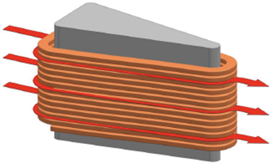
Illustration of the coolant flow path between the coil wires
The innovation of the rotor discs is in the way the magnets are retained in place at high speed and it took many iterations to arrive at a design that worked on a robust way at higher speeds. Traxial now plans to initially target manufacturers of E,F and S segment vehicles but is also open to opportunities within other segments and sectors if the business case makes sense. Typical eMobility customers are expected to be those requiring compact, lightweight motors with high power output and there is a clear vision that this technology will soon be powering the vehicles we all see and use.
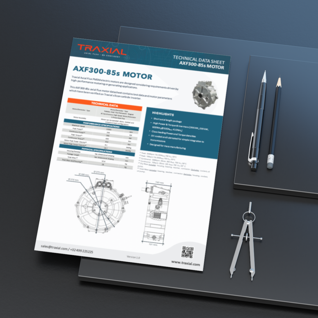
Get the technical data sheet of our latest axial flux motor, the AXF300-85s

This Post Has 0 Comments